| |
| |
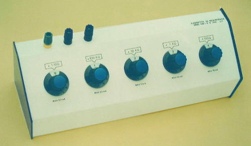
DECADE RESISTANCE BOX CRD and R1000 |
Resistance boxes with switches for laboratory.
 |
Accuracy: 1% both on ac and dc
Resistances of metallic layer with low temperature coefficent and high stability.
Switches with resistance of contact < 0,005W
Two input safety sockets plus earth connector
Power: 0,5W per resistance; For short period: 1W
Insulation voltage: 2000V
Realised on metallic box, oven-backed, internal connections made according to EEC rules.
|
CRD-4 - 4 Decade resistance boxes
- Available models:
| Model |
Decade steps in ohm |
Total ohm |
| CRD 142 R |
10 x (100+10+1+0,1) |
1.111 |
| CRD 143 R |
10 x (1k+100+10+1) |
11.110 |
| CRD 144 R |
10 x (10k+1k+100+10) |
111.100 |
| CRD 145 R |
10 x (100k+10k+1k+100) |
1.111.000 |
| CRD 146 R |
10 x (1M+100k+10k+1k) |
11.110.000 |
CRD-5 - 5 Decade resistance boxes
- Available models:
| Model |
Decade steps in ohm |
Total ohm |
| CRD 153 |
10x(1K+100+10+1+0,1) |
11.111 |
| CRD 154 |
10x(10K+1K+100+10+1) |
111.110 |
| CRD 155 |
10x(100K+10K+1K+100+10) |
1.111.100 |
| CRD 156 |
10x(1M+100K+10K+1K+100) |
11.111.000 |
CRD-6 - 6 Decade resistance boxes
Available models:
| Model |
Decade steps in ohm |
Total ohm |
| CRD 163 |
10x(10K+1K+100+10+1+0,1) |
111.111 |
| CRD 164 |
10x(100K+10K+1K+100+10+1) |
1.111.110 |
| CRD 165 |
10x(1M+100K+10K+1K+100+10) |
11.111.100 |
| CRD 166 |
10x(10M+1M+100K+10K+1K+100) |
111.111.000 |
Description
The R1000 consists of 7 resistor network which can be set by selector switches to the required value from 1 ohm to 9.999.999 ohm in steps of 1 ohm.
Resistors accuracy is +/- 1%.
Sockets provide access to every basic resistor network.
Switches enable series connection of basic resistor networks into one single value.
Series connection is interrupted in position "open" to enable one or a few networks to be used.
|
Technical data
Resistance range
--subranges
- 9X1
- 9X10
- 9X100
- 9X1k
- 9X10k
- 9X100k
- 9X1M
Frequency range
-- to 9 k ohm
--toa 9 M ohm
Accuracy
-- X 1ohm and X 10 ohm
-- X 100 ohm and for 1M ohm
|
0...99.99.999 ohm
0...9 ohm
0...90 ohm
0...900 ohm
0...9 k ohm
0...90 k ohm
0...900 k ohm
0...9 M ohm
to 10 M ohm
to 10 k ohm
+ 0 - 2% and + 0 - 0.08 ohm
+ 0 - 1%
|
Admitted load
Switch over-current
Admitted voltage
Admitted voltage between decades and housing
Dimensions
Weight
|
1W max
0.1 A max
100 V max
500 V max.
270 X 80 X 172mm
1.2 Kg
|
| |
| |
INDUCTANCE DECADE - L3000 |
Description
The L3000 consist of three decades made up of coils wound in ferrite pots and mounted on printed circuit boards.
Inductance on output terminals is set from 0 mH to 999 mH in steps of 1mH by three switches. Values are read-off directly from the front panel.
Inductance deviation from rated value is within limits of + 0 - 5% at In/2.
(In is the rated current loading given in the table for individual decade steps for which the declared inductance increases for 2%)
Permitted continous current loading to 100mA corresponds to most requirements occurring in every practice.
|
Technical data
Inductance range
--Three decades
X 100 mH
X 1.000 mH
X 10.000 mH
Accuracy in temp range from
15°C a 40°C a In/2
| 0...999 mH
0...9 mH
0...90 mH
0...900 mH
+ o - 5%
|
Inductance deviation (ðL/L)
due to current variation from In/2 to In
Capacitance between coils and housing
Test voltage against housing
Continous current load
Dimensions
Weight
|
2%
50 pF
1.5 kV
max. 100 mA
205 X 85 X 175mm
1.15 Kg
|
Description
The C2000 consist of three decades made of high-quality tropicalised styroflex capacitors with accuracy 1%.
Capacitance values on output terminals ca be set from 100pF to 100.000pF in steps of 100pF with three selector switches.
Switches and capacitors are protected by a special internal housing connected to a common terminal of all capacitors (central terminal) and fastened to the outer housing over insulation plates.
Capacitance between both housing is 100pF +/- 2% and is not added to the decade capacitance except when the upper terminal is connected to the external housing.
The extremely high d.c. insulation resistance of the C2000 allows the device to be used in d.c. circuits.
Permitted operating voltage corresponds to most requirements occuring in everyday practice.
To discharge the capacitor a pushbutton is used to connect the capacitor to earth via a 100kohm resistor.
|
Technical data
Capacitance range
--Three decades
X 100 pF
X 1.000 pF
X 10.000 pF
Accuracy
|
100...100.000pF
100...1.000 pF
1.000...9.000 pF
10.000...90.000 pF
+ 0 - 2%
|
Loss angle (tgð)
X 100 pF
X 1.000 pF
X 10.000 pF
|
max. 0.0005 a100 kHz
max. 0.0004 a10 kHz
max. 0.0004 a1 kHz
|
Max frequency
X 100 pF
X 1000 pF
X 10000 pF
|
9 MHz
2 MHz
500 KHz
|
Max operating volotage
Test voltage against
external housing
Capacitance between both housing
Insulating resistance
Capacitor discharging
Dimensions
Weight
|
400 V dc - 250 V ac
1.5kV ac
100 pF + o - 2%
min. 10000 m ohm
with pushbutton Discharge
on 100 k resistor
205 X 85 X 175 mm
1.35 Kg.
|
Copyright © 1995, italtec srl.
|
|
|